PRODUCTS
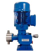
Plunger metering pumps type UG

Introduction
The dosing pumps type UG are studied to offer high reliability and metering precision also after a long working period.
The simple construction permits the maintenance operations to unexperienced personnel.
The pumps UG are manufactured according to the Standards 89/392 CE and following modifications.
Construction
The pump casing on which is installed the gear is made of die-cast aluminium and it is in monobloc execution, as well as the lantern of the pump head and the lantern of the motor.
The pumping head can be mde in different types of Stainless Steel or plastic materials.
The plunger is manufactured in different types of Stainless Steel or in Alumina.
Working principle
The dosing pumps type UG are plunger type with spring return.
The electric motor drives the plunger through a gear type worm and worm wheel installed in the pump casing. The wheel is installed on the side of the driving shaft that pushes the plunger through a cam.
The reurn of the plunger is assured by the releasing of the spring installed on the piston that is compressed during the pushing phase.
The gear is oil lubricated and it is supported at the ends by overdesigned ball bearings.
The flowrate can be adjusted manually or automatically with elctric or pneumatic strike positionners.
The adjusting system is based on a regulation micrometric screw with a rod that shuts the plunger stroke.
This system assures the dosing accuracy and the repeatibility.
The dosing range varies from 0 to 100% of the flowrate.
Electric motors
s are manufactured according to the Standards UNEL-MEC.
The main characteristics are: frame B14, eurovoltage, 3 phases, multyfrequency, mechanical protection IP 55 and insulation Cl F.
On request it is possible to install single phase motors.
| Type | Stroke mm | Plunger mm | Stroke/ min | Capacity max l/h | Pressure Bar | Connections | Motor Kw | ||
| 01-02 | 03 | 01-02 | 03 | ||||||
UG.0 UG.0 UG.0 UG.0 UG.0 UG.0 | 10 10 10 10 10 10 | 10 48 54 54 64 64 | 60 120 60 120 60 120 | 2.8 128 82 164 115 231 | 30 (150)** 8 6 6 4 4 | 10 8 6 6 4 4 | 3/8” Gm 1/2” Gm 3/4” Gr 3/4” Gr 3/4” Gr 3/4” Gr | 3/8” Gf 1/2” Gf 3/4” Gf 3/4” Gf 3/4” Gf 3/4” Gf | 0.25 0.25 0.37 0.37 0.37 0.37 |
| Pump head | A | B | ||
| 01 | 03 | 01 | 03 | |
| 10 20 25 38 48 54 64 | 200* 130 130 130 140 225 185 | 245* 160 160 185 190 215 215 | 120 120 120 125 150 150 115 | 120 120 120 140 150 145 145 |


